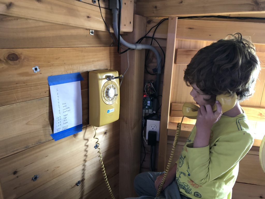
Rotary Phone & Pi
I wanted Max to use our old rotary phone, and with a little downtime during COVID and wanting to learn Python anyway, it was a great project to make the phone work on it’s own and to call another phone. Basically, I’m making my own little phone interchange, with the raspberry pi being the brains behind it all.
Challenges:
- Analog/rotary phones work on a 80V signal that is hard to make with 3V electronics on the Rasperry Pi board.
- Streaming audio from one phone to another without lags
Goals:
- Detect dialed numbers and do something depending on what number was dialed
- Play a dialtone when the phone is offhook
- Ring the phone, of course!
- Play audio, songs, etc. from memory card.
- Record audio and then have the pi call the phone back after a delay to play the audio back, potentially with modified higher or lower pitch
- Call another phone, making typical phone interchange sounds like dial tone, busy tone, ring tone, etc.
I started this project trying to use an Arduino with a Wave Shield, but after some work and sample code, it was nearly impossible to record audio with this setup. Since I also wanted to stream audio to another phone, I opted to explore the Raspberry Pi. Overall, I don’t think I’d go back to Arduino after playing around with the Pi boards. Why? because for the same price as an Arduino, you can get them with built-in wifi and connect through SSH to do bug fixes, backups, and log checks without having to unplug the system. Then there’s also the builtin USB, ETH, and HDMI ports which make setup and connecting peripherals really easy.
Code: Python Code is available on GitHub.
Resources:
- Rotary phone(s) with a working ringer.
- Raspberry pi 4 (Pi zero won’t work for streaming audio in both directions since it only has one processor)
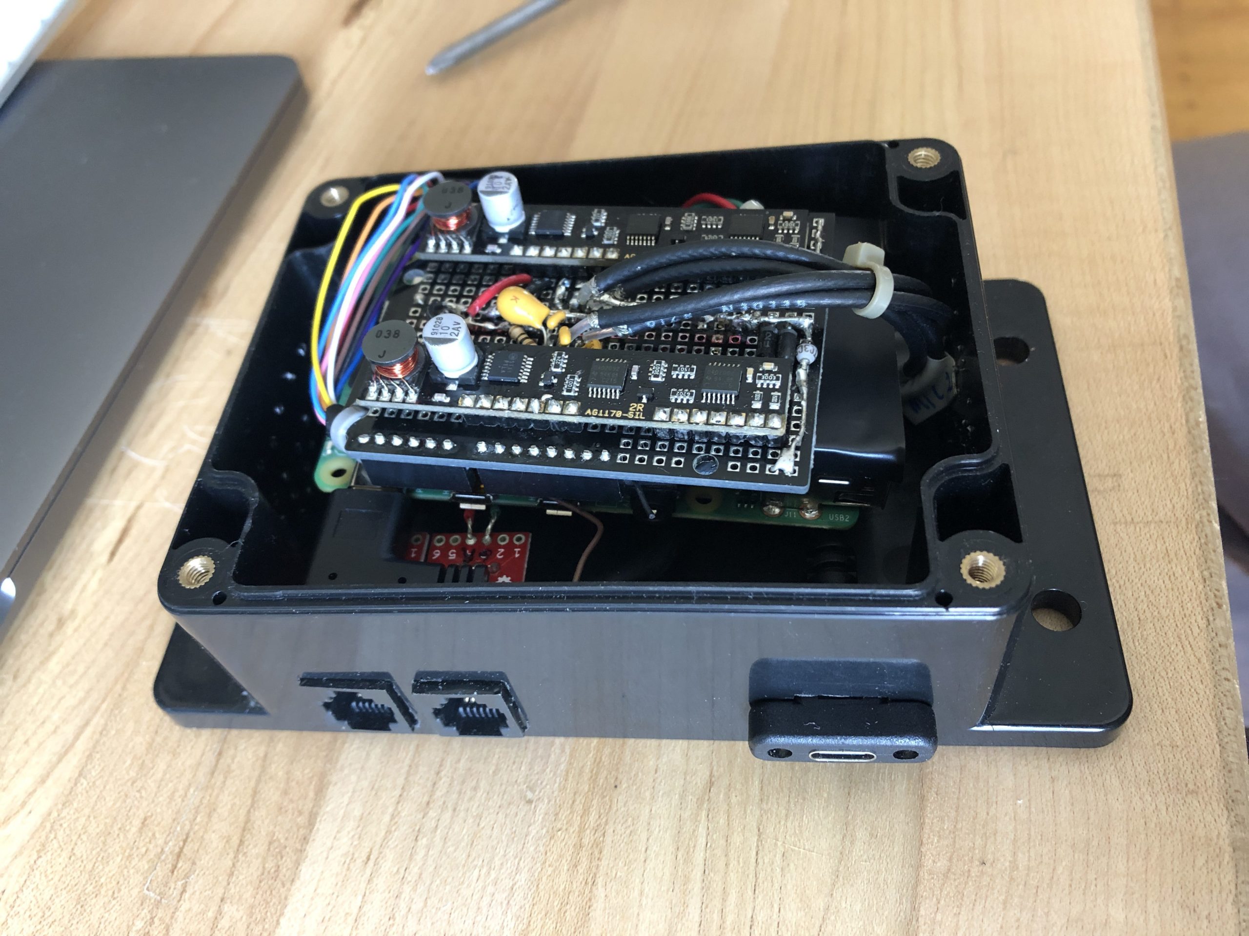
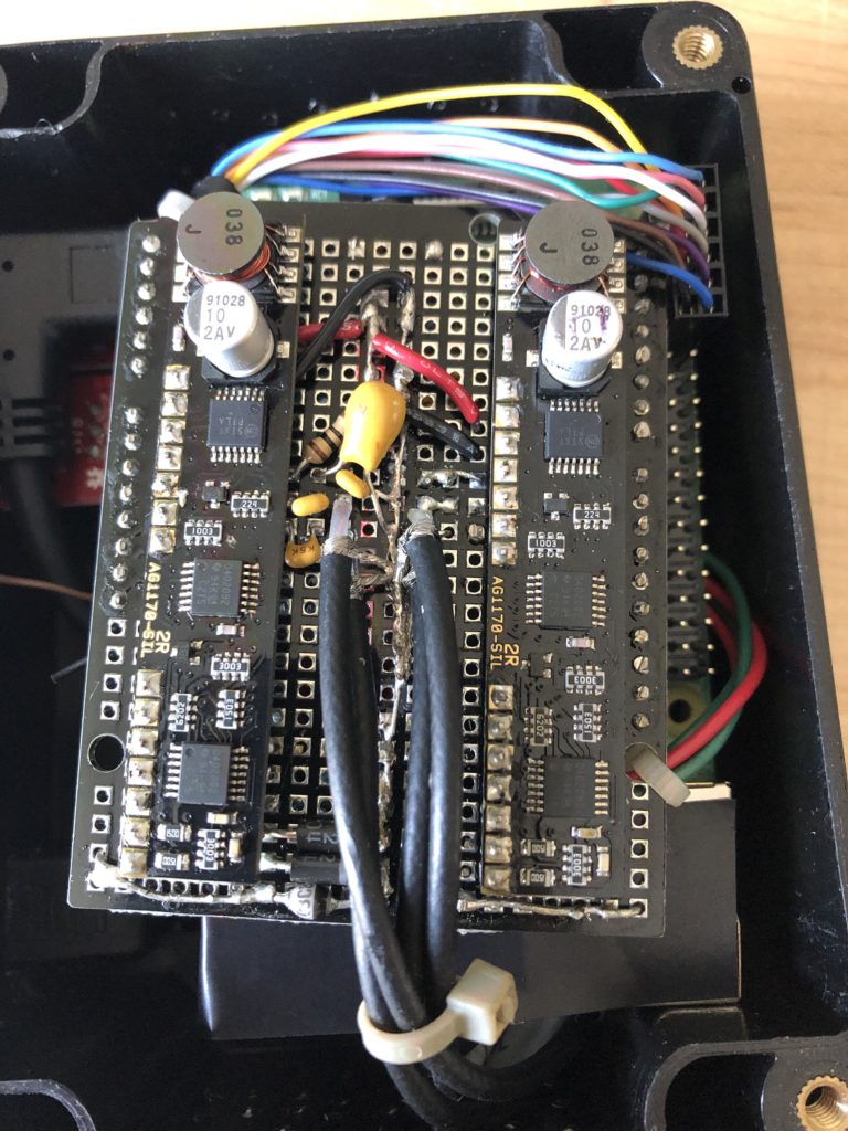
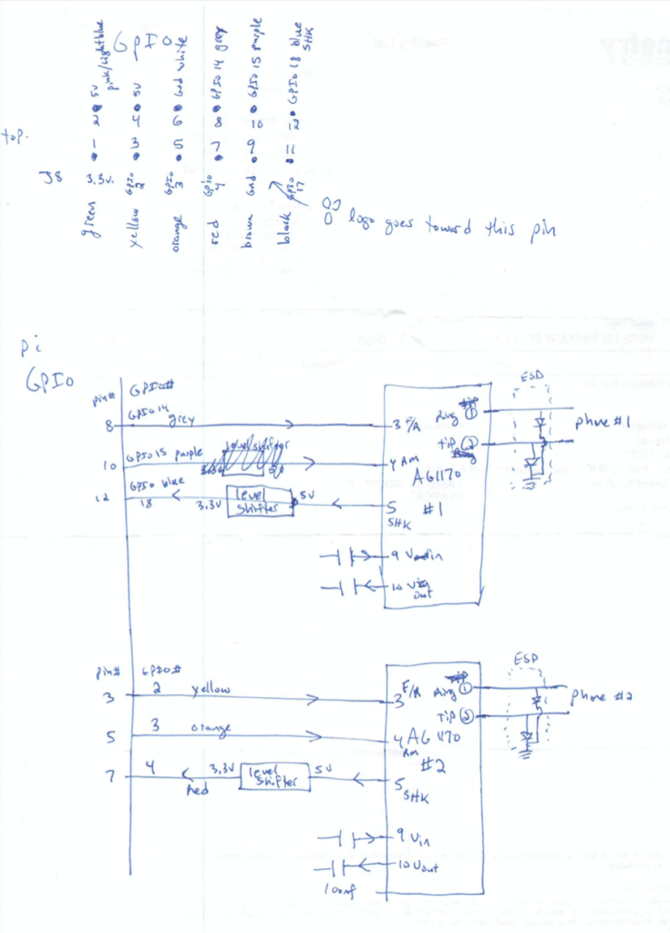
- AG1170-S3 Subscriber Line Interface Circuit + supporting circuitry from Digikey. (I bought the -S5 version, which works with 5V logic instead of the 3V required by raspberry pi, so I needed to use a Sparkfun level shifter to interface the two)
- 2 USB-audio adapters
- Box (all this just barely fits in the box I selected). I epoxied the phone jacks and such into the box after cutting the holes and filing them to the correct size.
- Power wiring
- Phone jacks & adapters (optional, but helpful)